An alternative Appoach to Realize 100W HF Tranceiver with RedPitaya or TS-680SDR
1. Introduction
It would be no doubt that Redpitaya is the next generation of Hermes introduced by TAPR for homebrew-radio amateurs. There are several approaches are introduced to be able to achieve 10W-100W HF tranceivers.
1) HAMLAB
Price tag is Euro699.00 including one RedPitaya and output power is 10W.
2) TAPR developed peripheral devices or second sources for Hermes
One example is described by KA6S as rf-adaptor project. I am not sure the additional cost but it will be around $500-$1,000.
The approach I describe here is a derivative of item 2). By utilizing non-SDR tranceiver hardware in the market, the additional cost keeps around $100.
2. TS-680SDR Project
I have one TS-680S and it is slept in my junk box for more than 20 years. It is a popular auction product and the average price is around $100.
Basic concept is
3. Details of proof of concept
Following pictures are the total view of the project. The center and the left is TS-680S and top of the right is RedPitaya. C-MOS to TTL level shifter board is located at the center of the left. Multiple attenuators are located at the bottom of the right and 10dB attenuator is actually selected.
1) RedPitaya OUTPUT1 to TS-680S
Problem of RedPitaya is the output level, 10mW, is less than 16dB smaller than Hermes and needs single stage RF amplifier to be able to drive TAPR provided Final board. On the contrary, TS-680S has the several RF levels at each TX stages, from such as 0.36V (0.25mW of Q81 output to 1.4V (40mW) of Q1 output according to the service manual. Therefore, I judged RedPitaya 10mW output is enough to drive the input (Q1) of the Final Unit. Actual connection can be seen the following picture.
To be able to obtain rated output of TS680S the fixed attenuators is adjusted and concluded 10dB is the best value.
Available output power is 100W from 1.8MHz to 21MHz, 50W from 24MHz to 29MHz and 10W at 50MHz bands. See the following picture of HPSDR PA Settings.
2) TS-680S preselector to RedPitaya INPUT1
I selected the point at the input of one of two FETs, Q18, Q19 and eliminated these twos. Actually I selected Q19.
By these connections, you can confirm that both receiver and transmitter paths are working by the manual operation from TS-680S front panel along with HPSDR software.
3) PTT, OUT from RedPitaya (Connector E1 DIO0_P)
There is sevelal candidate points for the selection and I picked up SS line, the output of SEND/REC switch , by the reason of the easy soldering. At this stage, you can confirm PTT control from HPSDR software via TS-680S controller.
4) LPF, HPF Selection from RedPitaya (Connector E1 DIO4_P ~ 7_P) (See alternative approach stated in item 5.2) )
It is a must to disconnect the control lines from TS-680S controller. I decided to disconnect the output of IC22 (8255) from pin 1 to pin 4 (A0 ~A3). I soldered the connection point at the input of 100 Ohm registors below the CN10.
You can confirm the LPF, HPF connection from HPSDR software at this stage and optimize the Hermes Ctrl Tag setting.
5) Level Shifters
The following bread board is the level shifters for PTT and LPF, HPF Selection. One base input registor wtih 4.7kohm and one PNP transistor for one level shifter.
6) CW functionality (Connector E1 Dot, In)
It looks like RedPitaya DIO1_N (Dash, In) does not input dash signal of keyer to mRXPS software. Thus, I decided to use external keyer (CwType) and connected Key-in output (DTS) to Dot, In (DIO2_N) and PTT (RTS) to PTT, IN (DIO0_N) through optical couplers. Then RedPitaya transmits CW signal.
However, TS-680S does not change the mode due to PTT, Out (DIO0_P) does not respond to external keyer PTT status change. Thus, I added the another optical coupler to CW Type PTT (RTS) to control TS-680S as well. Low latency is observed for RedPitaya CW generation.
7) Forward and Reverse Power Measurement
Connected VSF (VR17) and VSR (VR16) to AI0 and AI1 of RedPitaya Connector E2. Checked Alex of Hardware Config of General of Setup of mRX PS. Adjusted VR17 to display 100WForward Power at full Drive. Measured the registance of PWM by tester and ajusted VR16 to be the same value of VR17.
8) Puresignal
Tried two sniffer, one is 20dB two cores Stockton bridge built for 100W Power/SWR measuremnt and the other is 30dB single core built to Puresignal. Both works well though PA output flatness above 21MHz causes the degradation the performance.
4. Conclusion of Proof of Concept
I have started to use the proof of concept for digital (JT65/JT-9) and SSB operation. Therere is no inconvenience at this stage for the daily operation as SDR front panel-less box such as Flex or ANAN.

5. Next Plans at the Horizon
1) Complete the connection of remaining Connector E1 feature and Integrated RedPitaya to TS-680S inside
The following features are available
As the connection wires will be increased by the addition of features, it may be realistic to bring RedPitaya inside of TS-680S. The candidate is on SIGNAL board.
2) CAT Control (revised on 1/15/2018)
There is no existing transceiver control function provided by any SDR programs developed in the past. However the third party software exist to synchronize its SDR for bandscope application along with transceiver such as RigSynch. Utilizing this software, a CAT control USB line eliminates four lowpass and bandpass control lines and their level shifters stated in item 3.4). I have a home-made USB CAT controller board to control TS-680S and configured necessary software stated below.
RigSynch utilizes Omni-Rig to communicate with SDR program and TS-680S as RIG1 and RIG2. RigSynch periodically scans both RIG1 and RIG2 sending scanning "F comamnd" and obtains VFOA, VFOB, MODE information. By setting RIG2 as "Passive", RIG2 is always synchronized to RIG1 "ACTIVE". Therefore, TS-680S lowpass and bandpass filters follows the frequency change of SDR.
It is impractical to use USB CAT by the reason of delay of RigSynch and Omni-rig (a few hundred millisecond) and should use RedPitaya hardware control, i.e. E1 PTT OUT. This approach minimizes T-680S hardware change and necessary modification is two wires, OUT1 and IN1. If high speed CAT interface transceiver along with AI command after TS-870 series in Kenwood products is available, you may be able to enjoy smooth SDR frequency control by the dial of TS-870S.
I appreciate a RedPitaya community to develop the SDR firmwares especially Pavel.
3) Complete integration with RedPitaya with minimum additional peripheral hardware (Revised on 10/16/2018)
I tried to realize all features available with OpenHPSDR mRX PS (eliminating additional peripheral interface such as TPIC6B595 or PCA9555 described in Pavel's documatation. All connections are E1, E2 and USB connector.
Available features are;
1) TS-680S CAT control through RedPitaya USB interface
2) WM8731Codec Proto board connected to E1 I2S and E2 I2C (Hermes Built-in Mic and speaker)
3) PE4302 evaluatiion board connected to E2 SPI (Step-attenuator for PureSignal Auto-Attenuate)
4) RedPitaya built-in Lambic CW paddles connected to E1 Dash and Dot pins)

Optional peripheral interface required for dual receivers are mechanical switch(es) to select either received antenna or puresignal sniffer signal controlled by E1 PPT-out pin. They locates at the top-right of universal PCB. To be able to control CAT via USB port and PE4302, I modified sdr-transceiver-hpsdr.c program.
Pros:
1. Minimum additional peripherals.
2. Most economical configuration to realize Hermes and Metis compatible board by RedPitaya
Cons:
1. Complex and ugly jumper cables connecting E1 and E2 pins and universal PCB (total 17 pins on E1 and E2 are used). It is impossible to mount universal PCB into TS-680S.
2. WM8731 codec (aiming for MP3 earphone and mic portable application) proto board does not have Line-in and Line-out connectors. Thus, mic and speaker audio quality are poor compare to PC audio codec.
3. RedPitaya SPI interface capability is limited to one chip selection. Thus, we can not add another PE4302 for Drive level control.
It would be no doubt that Redpitaya is the next generation of Hermes introduced by TAPR for homebrew-radio amateurs. There are several approaches are introduced to be able to achieve 10W-100W HF tranceivers.
1) HAMLAB
Price tag is Euro699.00 including one RedPitaya and output power is 10W.
2) TAPR developed peripheral devices or second sources for Hermes
One example is described by KA6S as rf-adaptor project. I am not sure the additional cost but it will be around $500-$1,000.
The approach I describe here is a derivative of item 2). By utilizing non-SDR tranceiver hardware in the market, the additional cost keeps around $100.
2. TS-680SDR Project
I have one TS-680S and it is slept in my junk box for more than 20 years. It is a popular auction product and the average price is around $100.
Basic concept is
- Connect RedPitaya OUT1 to TS-680S 100W Final Unit input
- Connect RedPitaya IN1 to TS-680S Presector output in Signal Unit
- Connect RedPitaya Connector E1 to TS-680S Control Unit (See alternative approach stated in item 5.2)
3. Details of proof of concept
Following pictures are the total view of the project. The center and the left is TS-680S and top of the right is RedPitaya. C-MOS to TTL level shifter board is located at the center of the left. Multiple attenuators are located at the bottom of the right and 10dB attenuator is actually selected.
 |
| Top View of the Project |
 |
| Bottom View of the Project |
Problem of RedPitaya is the output level, 10mW, is less than 16dB smaller than Hermes and needs single stage RF amplifier to be able to drive TAPR provided Final board. On the contrary, TS-680S has the several RF levels at each TX stages, from such as 0.36V (0.25mW of Q81 output to 1.4V (40mW) of Q1 output according to the service manual. Therefore, I judged RedPitaya 10mW output is enough to drive the input (Q1) of the Final Unit. Actual connection can be seen the following picture.
 |
| Three Stage 100W Final Unit Circuits |
 |
| Connection of RedPitaya Output |
 |
| 10dB attenuator is used |
 |
| HPSDR PA Setting Tag |
2) TS-680S preselector to RedPitaya INPUT1
I selected the point at the input of one of two FETs, Q18, Q19 and eliminated these twos. Actually I selected Q19.
 |
| Preselector and Q18, Q19 FETS |
 |
| Connection to RedPitaya INPUT1 |
3) PTT, OUT from RedPitaya (Connector E1 DIO0_P)
There is sevelal candidate points for the selection and I picked up SS line, the output of SEND/REC switch , by the reason of the easy soldering. At this stage, you can confirm PTT control from HPSDR software via TS-680S controller.
 |
| SS Line |
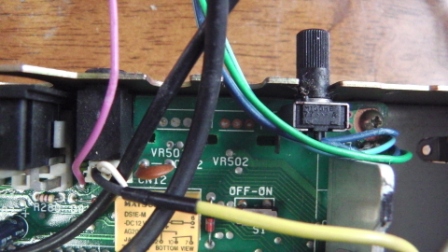 |
| PTT out line (viored color) |
It is a must to disconnect the control lines from TS-680S controller. I decided to disconnect the output of IC22 (8255) from pin 1 to pin 4 (A0 ~A3). I soldered the connection point at the input of 100 Ohm registors below the CN10.
 |
| IC22 and CN10 Circuits |
 |
| Disconnection from IC22 (top of the left) and Connection to RedPitaya |
You can confirm the LPF, HPF connection from HPSDR software at this stage and optimize the Hermes Ctrl Tag setting.
 |
| HPSDR Hermes Ctrl Tag Setting |
5) Level Shifters
The following bread board is the level shifters for PTT and LPF, HPF Selection. One base input registor wtih 4.7kohm and one PNP transistor for one level shifter.
 |
| C-MOS to TTL Level Shifters |
6) CW functionality (Connector E1 Dot, In)
It looks like RedPitaya DIO1_N (Dash, In) does not input dash signal of keyer to mRXPS software. Thus, I decided to use external keyer (CwType) and connected Key-in output (DTS) to Dot, In (DIO2_N) and PTT (RTS) to PTT, IN (DIO0_N) through optical couplers. Then RedPitaya transmits CW signal.
However, TS-680S does not change the mode due to PTT, Out (DIO0_P) does not respond to external keyer PTT status change. Thus, I added the another optical coupler to CW Type PTT (RTS) to control TS-680S as well. Low latency is observed for RedPitaya CW generation.
7) Forward and Reverse Power Measurement
Connected VSF (VR17) and VSR (VR16) to AI0 and AI1 of RedPitaya Connector E2. Checked Alex of Hardware Config of General of Setup of mRX PS. Adjusted VR17 to display 100WForward Power at full Drive. Measured the registance of PWM by tester and ajusted VR16 to be the same value of VR17.
 |
| Front- Power mearing Cable (Back-Preselector Cable) |
 |
| Fwd SWR TX Meter Both Fwd Power and SWR are displayed |
Tried two sniffer, one is 20dB two cores Stockton bridge built for 100W Power/SWR measuremnt and the other is 30dB single core built to Puresignal. Both works well though PA output flatness above 21MHz causes the degradation the performance.
 |
| IMD -58 dB at 7MHz |
4. Conclusion of Proof of Concept
I have started to use the proof of concept for digital (JT65/JT-9) and SSB operation. Therere is no inconvenience at this stage for the daily operation as SDR front panel-less box such as Flex or ANAN.

At the center postion of the desktop
Actually, this approach is a free-upgrade from 10mW to 100W output and to avoid jams from intereferes as I picked up all necessary parts from my Junk box.5. Next Plans at the Horizon
1) Complete the connection of remaining Connector E1 feature and Integrated RedPitaya to TS-680S inside
The following features are available
Power/SDR Reading from HPSDR software (Connector E2 Analog inpt 0 and 1)(Done on 12/13/2016)CW functionality (Connector E1 Dot, In)(Done on 12/04/2016)Pure Signal(Done on 12/30/2016)
As the connection wires will be increased by the addition of features, it may be realistic to bring RedPitaya inside of TS-680S. The candidate is on SIGNAL board.
2) CAT Control (revised on 1/15/2018)
There is no existing transceiver control function provided by any SDR programs developed in the past. However the third party software exist to synchronize its SDR for bandscope application along with transceiver such as RigSynch. Utilizing this software, a CAT control USB line eliminates four lowpass and bandpass control lines and their level shifters stated in item 3.4). I have a home-made USB CAT controller board to control TS-680S and configured necessary software stated below.
 |
| Home-built USB CAT Controller for TS-680S |
RigSynch utilizes Omni-Rig to communicate with SDR program and TS-680S as RIG1 and RIG2. RigSynch periodically scans both RIG1 and RIG2 sending scanning "F comamnd" and obtains VFOA, VFOB, MODE information. By setting RIG2 as "Passive", RIG2 is always synchronized to RIG1 "ACTIVE". Therefore, TS-680S lowpass and bandpass filters follows the frequency change of SDR.
 |
| TS-680S follow SDR via RigSynch |
It is impractical to use USB CAT by the reason of delay of RigSynch and Omni-rig (a few hundred millisecond) and should use RedPitaya hardware control, i.e. E1 PTT OUT. This approach minimizes T-680S hardware change and necessary modification is two wires, OUT1 and IN1. If high speed CAT interface transceiver along with AI command after TS-870 series in Kenwood products is available, you may be able to enjoy smooth SDR frequency control by the dial of TS-870S.
I appreciate a RedPitaya community to develop the SDR firmwares especially Pavel.
3) Complete integration with RedPitaya with minimum additional peripheral hardware (Revised on 10/16/2018)
I tried to realize all features available with OpenHPSDR mRX PS (eliminating additional peripheral interface such as TPIC6B595 or PCA9555 described in Pavel's documatation. All connections are E1, E2 and USB connector.
Available features are;
1) TS-680S CAT control through RedPitaya USB interface
2) WM8731Codec Proto board connected to E1 I2S and E2 I2C (Hermes Built-in Mic and speaker)
3) PE4302 evaluatiion board connected to E2 SPI (Step-attenuator for PureSignal Auto-Attenuate)
4) RedPitaya built-in Lambic CW paddles connected to E1 Dash and Dot pins)

Optional peripheral interface required for dual receivers are mechanical switch(es) to select either received antenna or puresignal sniffer signal controlled by E1 PPT-out pin. They locates at the top-right of universal PCB. To be able to control CAT via USB port and PE4302, I modified sdr-transceiver-hpsdr.c program.
Pros:
1. Minimum additional peripherals.
2. Most economical configuration to realize Hermes and Metis compatible board by RedPitaya
Cons:
1. Complex and ugly jumper cables connecting E1 and E2 pins and universal PCB (total 17 pins on E1 and E2 are used). It is impossible to mount universal PCB into TS-680S.
2. WM8731 codec (aiming for MP3 earphone and mic portable application) proto board does not have Line-in and Line-out connectors. Thus, mic and speaker audio quality are poor compare to PC audio codec.
3. RedPitaya SPI interface capability is limited to one chip selection. Thus, we can not add another PE4302 for Drive level control.


コメント
コメントを投稿